|
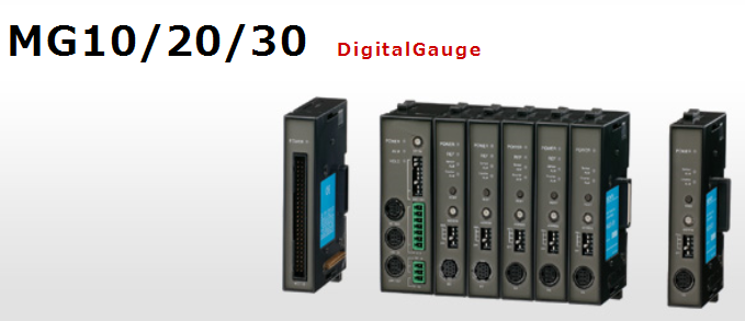
MG10-P1 |
MG10-P2 |
| Power |
Power supply Power supply voltage |
DC12~24V(11~26.4V)Min. startup time: :100ms or less |
| Power consumption |
2.0W +total power consumption for connected modules※1 |
| Imrush current(10ms ) |
10Aor less(when maximum number of modules are connected) |
| Power supply reverse connection prevention |
Fuse(5A fuse is built in.) |
| Communication |
I/F input/ output circuit |
RS‐ 232C(Conforms to EIA-232C) |
| Baud rate setting |
2400/9600/19200/38400 bps(set with DIP switch) |
| Data length |
7/8bit(set with DIP switch) |
| Stop bit |
1/2bit(set with DIP switch) |
| Parity |
None/ODD/EVEN(set with DIP switch) |
| Delimiter |
CR/CR+LF(set with DIP switch) |
| Linkage function |
Maximum number of linkages |
max.16(total of counter modules64) |
| Maximum length of linking cable |
max.10m |
| I/O
|
| Input format |
source input(+COM) |
sink input(-COM) |
| Photo coupler insulationDC 5~24V |
| Output format |
sink type(-COM) |
source type(+COM ) |
| Photo coupler insulationDC 5~24V |
| Input signal |
reset, pause, start, latching, and data out trigger to whole channels |
| Output signal |
integrated alarm |
| Connectable modules |
Counter modules |
MG20-DK, MG20-DG, MG20-DT (available for mixed use, up to 16 modules)※1 |
| Interface modules |
MG30‐ B1, MG30‐B2※1 |